LCD FeatherWing
The LCD FeatherWing is a low-power display compatible with Adafruit’s Feather line of development boards. It uses the BU9796 segment LCD controller to drive a custom liquid crystal display glass with 48 segments, including:
- Five indicator icons: Bell, Wifi, Moon, Arrows and Battery
- Five 7-segment digits, plus a sign indicator
- Four decimal points, one between each pair of digits
- AM and PM indicators, plus a colon for displaying the time

Contents
- Assembly Instructions
- CircuitPython usage
- Arduino usage
- Notes for both platforms
- Putting It All Together: a Simple Clock App
- Advanced Configuration
Assembly Instructions
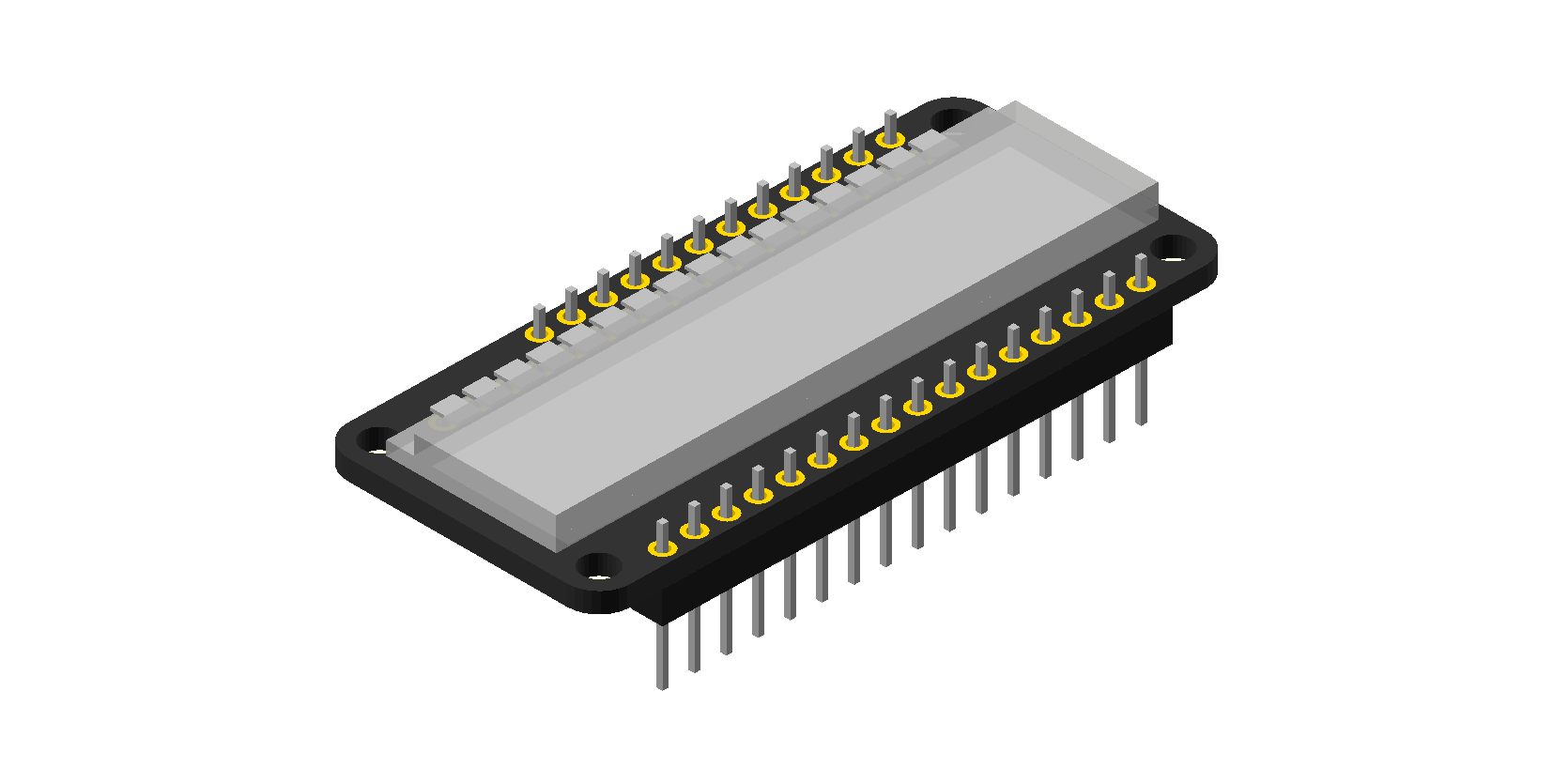
First, insert the LCD glass on the front of the wing (the side with the big white box). Then flip the wing over, and solder the LCD pins into the through holes on the back.
Next, insert the Feather headers from the back, and solder them in on the front.
Usage
Libraries exist for both CircuitPython and Arduino, so you can get started quickly.
CircuitPython Usage
- Download the Adafruit library and driver bundle, as well as the CircuitPython driver for LCD FeatherWing.
- Plug in your Feather board running CircyutPython, and ensure that you can see the
CIRCUITPYdrive on your computer. - Copy both the
adafruit_bus_devicefolder and theoso_lcdfolder to your board’slibfolder.
You’re done! Now you can instantiate the LCD driver and write to the display like so:
import board
from oso_lcd.lcdwing_lite import LCDWingLite

display = LCDWingLite(board.I2C())
display.print("HELLO")
From here, skip ahead to the notes for both platforms section for more details about working with the LCD.
Arduino Usage
In the Arduino library manager, search for and install the “Oddly Specific Objects LCD FeatherWing Library”. It may ask about a dependency, the “Adafruit Bus Device” library. If it does, make sure to install that library too.
Now, you can instantiate the LCD driver (after #includeing OSO_LCD.h):
OSO_LCDWing display;
if (!display.begin()) {
    while (1) Serial.println("ERR");
}
This checks to make sure that the LCD driver initialized successfully, and displays an error message on the serial terminal if it did not.
You can clear the LCD like this:
display.fill(0);and energize all segments like so:
display.fill(1);Printing text to the LCD is easy:
display.print("hello");For more details, read onto the next section, notes for both platforms.
Notes for Both Platforms
Whether you are using CircuitPython or Arduino, the API for both platforms is largely identical, as is the character set. These guidelines apply to both platforms, and where syntax differences exist, the difference will be called out and the syntax described for each.
Character Set Notes
The character set in the LCD FeatherWing library displays characters in mixed case in order to give each character a unique representation. Both uppercase and lowercase letters in your string display in the case chosen by the library; there is no difference between display.print("ABCDE") and display.print("abcde"). A appears as uppercase, but B and D appear as lowercase to distinguish them from the 8 and 0 characters:

Similarly, C appears in lowercase to distinguish it from the open parenthesis (, as seen here when we display.print("(789)"):

Some characters simply don’t work well as a seven-segment digit. In this example, we’ve called display.print("Wifi") and display.print("Main"). The W appears as an upside down A, and the M appears as a tall N:


If you are willing to sacrifice two characters, you can display these letters using some two character codes: $J displays a W, and &7 displays an M. So you could display “Wifi” by calling display.print("$Jifi"), or “Main” by calling display.print("&7ain"):


Finally, there’s one character that doesn’t do what you would expect. Since the # symbol doesn’t translate well to a 7-segment display, the library uses this character to display the degree symbol. So if you wanted to display a temperature of 72.4° F, you would do it like so: display.print("72.4#F").

The Colon
When you call display.print, the LCD FeatherWing library automatically sets the colon if there is a colon in the appropriate spot (usually the third character in a string). So, for example, calling display.print("12:34") will set the colon.

However, calling display.print("1:23") will not set the colon.

Instead, add a space before: display.print(" 1:23"). The additional space at the beginning of the string pushes the colon to the correct spot.

There is also a special method to toggle the colon. Call display.toggle_colon() and it will set the colon to the opposite of its current state: if it was on, it turns off, and if it was off it turns on. Calling this method twice a second is a good way to display a clock ticking.
Sign Indicator and Decimal Points
If the first character in your string is a minus sign (-), the LCD FeatherWing library will set the sign indicator to the left of the digits instead of putting the sign in the first digit. This means that you can display any number from -99999 to 99999.


It also means that if you are using the colon, it will be expected in the fourth position instead of the third, as in this countdown clock: display.print("-10:00.0").

There are four decimal points, one between each digit. The LCD FeatherWing library will automatically set the appropriate decimal point if it is included in your string, unless it occurs before the first digit or after the last one. This is because there is no decimal point to the left of the first digit or the right of the last one. So, for example, display.print(".1234") will display incorrectly, but display.print("0.1234") will work. Similarly, display.print("Thurs.") will omit the period at the end, but display.print("Thur.") will display it.


Indicator Icons
There are seven indicators on the LCD, including five icons as well as the AM and PM indicators on the right.

You can control these indicators using the set_indicator and clear_indicator methods, but note that the names you pass to these functions differ between CircuitPython and Arduino.
CircuitPython indicator names
The indicator names are defined in the Indicator class in the lcdwing_lite module. Their definitions, clockwise from top left:
Indicator.BELLIndicator.WIFIIndicator.AMIndicator.PMIndicator.BATTERYIndicator.DATA(the paired arrows)Indicator.MOON
There is also a special value, Indicator.ALL, that is useful to clear all indicators at once: display.clear_indicator(Indicator.ALL).
Arduino indicator names
The indicator names are constants defined in OSO_LCD.h. Their names, clockwise from top left:
OSO_INDICATOR_BELLOSO_INDICATOR_WIFIOSO_INDICATOR_AMOSO_INDICATOR_PMOSO_INDICATOR_BATTERYOSO_INDICATOR_DATA(the paired arrows)OSO_INDICATOR_MOON
There is also a special value, OSO_INDICATOR_ALL, that is useful to clear all indicators at once: display.clear_indicator(OSO_INDICATOR_ALL).
Putting It All Together: a Simple Clock App

CircuitPython
This Python script is available in the examples folder of the LCD FeatherWing CircuitPython library. It’s a simple clock that uses CircuitPython’s built-in RTC module to display the current time.
import board
import time
import rtc
from oso_lcd.lcdwing_lite import LCDWingLite, Indicator

display = LCDWingLite(board.I2C())
minute = None
clock = rtc.RTC()
clock.datetime = time.struct_time((2022, 6, 30, 11, 59, 55, 0, -1, -1))

while True:
    if minute != clock.datetime.tm_min:
        dt = clock.datetime
        hour = dt.tm_hour % 12
        minute = dt.tm_min
        display.clear_indicator(Indicator.ALL)
        display.print("{:2d}:{:02d}".format(hour if hour else 12, minute))
        if dt.tm_hour < 12:
            display.set_indicator(Indicator.AM)
        else:
            display.set_indicator(Indicator.PM)
    display.toggle_colon()
    time.sleep(0.5)
Arduino
This Arduino sketch is available in the examples folder of the LCD FeatherWing Arduino library. It functions identically to the CircuitPython script above. Note that it is designed for the Feather M0, and requires the ZeroRTC library.
#include <OSO_LCD.h>
#include <RTCZero.h>

RTCZero rtc;
OSO_LCDWing display;

void setup() {
    rtc.begin();
    if (!display.begin()) {
        while (1) Serial.println("ERR");
    }
    display.fill(0);
    rtc.setHours(11);
    rtc.setMinutes(59);
    rtc.setSeconds(55);
}

int minute = -1;
char buf[10];

void loop() {
    int newMinute = rtc.getMinutes();

    if (minute != newMinute) {
        int hours = rtc.getHours() % 12;
        minute = newMinute;
        sprintf(buf, "%2d%02d ", hours ? hours : 12, minute);
        display.clear_indicator(OSO_INDICATOR_ALL);
        if (rtc.getHours() < 12) {
            display.set_indicator(OSO_INDICATOR_AM);
        } else {
            display.set_indicator(OSO_INDICATOR_PM);
        }
        display.print(buf);
    }
    display.toggle_colon();

    delay(500);
}
Resources
- LCD FeatherWing CircuitPython library
- LCD FeatherWing Arduino library
- Design files for LCD wing and custom LCD
- BU9796 data sheet
Advanced Configuration
There are two solder jumpers on the back of the circuit board that allow for advanced configuration. In general, you don’t need to do anything to them, but they can be useful in some specific cases.
JP1: Software Contrast Control
JP1 allows you to control the LCD driving voltage using the DAC pin on an ESP32 Feather or a Feather M4. This can be useful to lower the contrast of the display if you intend to view it from an extreme angle.
To enable this functionality, use an Exacto knife to cut the bridge connecting JP1 to the pad on the right (GND). Then use a blob of solder to bridge the center pad to the left pad (A0).
Now, the voltage on A0 will define the LCD voltage according to the following formula: VLCD = 3.3 - A0. Setting A0 to 0 V will drive the LCD at 3.3 volts; setting A0 to 0.3 V will drive it at 3.0 volts, etc.
SDA and SCL jumpers: alternate I²C bus
The BU9796 has no address pins, so you can only drive one display on an I²C bus. However, some Feather boards can support two or even more I²C buses! By soldering wires to these pads and rerouting some signals, you can drive multiple LCD FeahterWings from one Feather.
Please note: THIS IS AN ADVANCED HACK and it’s easy to inadvertently cut a trace, pull a pad or knock off a surface mount resistor while doing this. Please only attempt this if you feel comfortable working in a very small area.
To do this hack, fully cut the bridge connecting the top and bottom of the SDA and SCL jumpers. Then solder a wire to the BOTTOM half of the jumper. Connect the other side of the wire to an alternate SDA or SCL pin.
Some guidance on which pins work:
ESP32/S2/S3 and NRF52840 Feathers
These devices have two I²C peripherals. In addition to the main I²C bus on SDA and SCL, any two pins can function as a second I²C bus.
Feather M0 and M0 Express
These devices can support up to four I²C buses. In addition to the main I²C bus on SDA and SCL, you can use the following pins to create three additional I²C buses:
- A1 (SDA) and A2 (SCL) *
- A3 (SDA) and A4 (SCL)
- 11 (SDA) and 13 (SCL)
* Note that in this configuration, you will be unable to use the SPI pins as an SPI bus, although they’ll still work fine as GPIO.
Feather M4 Express
This device can support up to SIX I²C buses! In addition to the main I²C bus on SDA and SCL, you can use the following pins to create five additional I²C buses:
- A2 (SDA) and A3 (SCL)
- A4 (SDA) and A1 (SCL)
- 12 (SDA) and 13 (SCL)
- TX (SDA) and RX (SCL)
- 5 (SDA) and SCK (SCL)